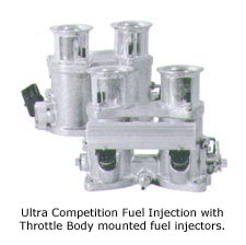
Installing
a set of dual throttle bodies is a lot like bolting on a set of dual
carburetors. One key point is that throttle bodies are manufactured
in left and right side models. This makes throttle bodies easier to
deal with than a set of dual IDF Webers which are only available in
right side configurations.
The first step
to your Ultra Competition Fuel Injection Kit is to start with your fuel
system. You'll have to scrap your old fuel system and pump because you're
going to require a modern fuel delivery system. One similar to that
used on all new automobiles where fuel is pumped from the tank, to the
injectors and pressure regulator under high pressure. Fuel then returns
to the tank at reduced pressure. A continuous supply of fuel is circulated
throughout the system. The fuel pressure is regulated according to the
engines requirements.
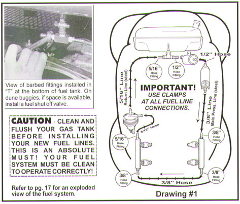
Replace the present
fuel outlet at the bottom of your tank with the "T" supplied
in your kit. These are two supplied brass barbed fittings. One ¼"
NPT x ½" hose (to the fuel filter - main fuel supply) and
one ¼" NPT x 5/16" hose (used for the return line of
the fuel system). Be sure to use teflon tape on all fuel fittings. Make
certain not to get any excess Teflon or strings of Teflon into the fuel
system.
Mount the fuel
filter and fuel pump under the fuel tank and below the fuel level. Use
the supplied ½" hose to connect the fuel filter to the "T"
and the other side of the filter to the pump. Be sure to have the fuel
from the tank enter the fuel filter before it passes through the fuel
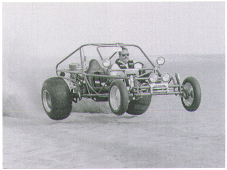
pump. Installation is easy in a race car or dune buggy because most
of these have rear mounted fuel tanks. Make certain to use clamps on
all connections.
Installation in
a VW sedan is a little more complicated because it requires the installation
of two steel fuel lines. One 3/8" line, used for the main pressure
line from the pump to one of the throttle bodies and one 5/16"
line for the return from the regulator to the tank. On sedan installations,
the lines can be run so that one line goes down the passenger side of
the car (main line) and the other goes down the drivers side of the
car (return line), or vice versa depending on how you choose to route
the main and return lines. Doing it this way creates a big circle. Fuel
comes from the tank, to both throttle bodies, to the regulator and back
to the tank again. How ever you decide on mounting the fuel lines for
your system, make sure to use the ½" fitting as the main
fuel supply to the engine and the 5/16" fitting as the return to
the tank. These lines will be running the length of the car, rubber
fuel line is not an option here!
 Rubber line can be used to connect all hard line connections.
Where ever a connection is to be made using rubber line, do not use
normal fuel line, use only high pressure fuel line!
When securing the hard lines to the bottom of your car, use some type
of rubberized clamp to help reduce vibration. On a buggy, you naturally
won't have to run your line from the front of the vehicle to the back,
in this case rubber line would be acceptable. Make certain to have your
lines secure and away from heat and any moving parts. Again, use only
high pressure fuel line, especially if your complete system will consist
of rubber line. This refers to buggies only though, not sedans or any
other type of vehicle where the lines will need to run the entire length
of the vehicle! Refer to (drawing #1 on this pg.) for illustration on
running your fuel system.
Rubber line can be used to connect all hard line connections.
Where ever a connection is to be made using rubber line, do not use
normal fuel line, use only high pressure fuel line!
When securing the hard lines to the bottom of your car, use some type
of rubberized clamp to help reduce vibration. On a buggy, you naturally
won't have to run your line from the front of the vehicle to the back,
in this case rubber line would be acceptable. Make certain to have your
lines secure and away from heat and any moving parts. Again, use only
high pressure fuel line, especially if your complete system will consist
of rubber line. This refers to buggies only though, not sedans or any
other type of vehicle where the lines will need to run the entire length
of the vehicle! Refer to (drawing #1 on this pg.) for illustration on
running your fuel system.
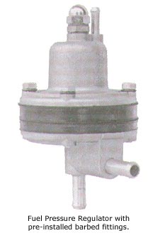 Two
styles of Fuel Pressure Regulators are available. One is tapped for
1/8" NPT and the other has pre-installed 5/16" fittings. The
regulator can be secured to one end of the fuel rail, firewall, engine,
frame or where ever convenient. Do not mount the regulator on or near
the exhaust or any type of heat source. There are too many variables
for us to point out one specific location for the installer to mount
the fuel pressure regulator.
Two
styles of Fuel Pressure Regulators are available. One is tapped for
1/8" NPT and the other has pre-installed 5/16" fittings. The
regulator can be secured to one end of the fuel rail, firewall, engine,
frame or where ever convenient. Do not mount the regulator on or near
the exhaust or any type of heat source. There are too many variables
for us to point out one specific location for the installer to mount
the fuel pressure regulator.
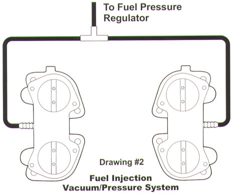
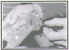
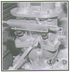
Before the pre-assembly
procedure of the throttle bodies and manifolds begins, it's always a
good idea to pre-tune your throttle bodies. Balancing and dialing in
a set of dual throttle bodies can be greatly simplified by making certain
that each throttle body is adjusted to the same idle speed setting before
you bolt 'em on. Let's call it pre-tuning. You can pre-tune your throttle
bodies by sliding a .003" feeler gauge between the butterfly and
throttle bore. Adjust the idle speed screw until you can feel a snug
.003" fit between the butterfly and the wall of the throttle bore.
Make certain that both throttle bodies are set at the same .003"
opening. Check only the butterflies nearest the idle speed adjusting
screws.
|
Throttle
Bodies can be set by adjusting the butterfly to wall clearance
with a .003" feeler gauge. Check only the butterfly closest
to the idle speed control screw. This procedure will provide equal
flow through each throttle body. You can then further balance
the throttle bodies with a uni-Syn gauge with the engine running. |
The idle speed throttle
settings obtained in this manner might not be exactly what your engine
requires to idle at a desired speed, but they will be reasonably in sync.
Increasing or decreasing the idle speed is just a matter of turning the
idle speed control screws in or out ½ turn at a time until a desired
speed is reached. In for more idle speed and out for less idle speed.
Be sure to adjust the idle speed screws equal and this will keep both
throttles bodies closely in sync. The function of the throttle bodies
is to control air flow. The trick is to start out even and keep them even
throughout the opening and closing cycle. The feeler gauge is a good starting
point, but the finishing touch to a good balance job is the use of a Uni-Syn
gauge, we'll get into that procedure later.
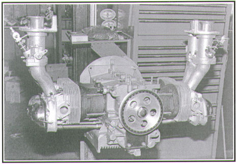
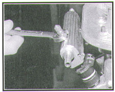
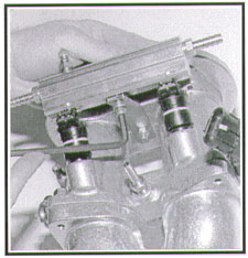
Start by bolting
the throttle bodies to the intake manifolds. Each throttle body is held
is held in position by four 8mm studs. Thread the short end of the studs
into the manifolds and tighten them by double locking two nuts. This
technique requires the use of two wrenches, but it assures you that
the studs won't back out later. When you have secured all the studs,
install the base gasket and position the the throttle bodies on the
manifolds. Place one washer on each mounting stud, thread the nuts on
and torque them down to twelve pounds.
Now determine
which throttle body will serve as the right side assembly and which
one will be the left side assembly. Keep in mind that the throttle linkage
control arms face the rear of the engine. That's the end of the engine
with the fan belt. When the throttle bodies are installed and sitting
at closed idle speed, the throttle shaft control arms tilt in at about
45 degrees towards the center line of the engine. The TPS (Throttle
Position Sensor) should be on the right side throttle body and face
the flywheel end of the engine. On Sedan Competition applications, the
throttle bodies will be the exact opposite of what was just explained.
The injectors will be inboard and the TPS switch will be on the drivers
side throttle body facing the flywheel side of the engine. The throttle
control arms should still be on the pulley side, but will tilt away
from the center of the engine. (Refer
to pg.4 for illustration).
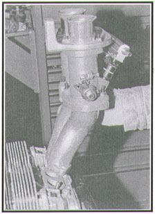
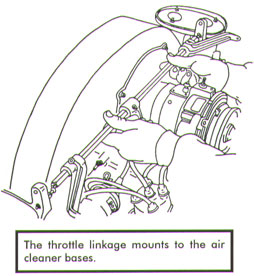
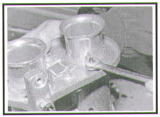 With
the throttle bodies mounted and secured to the intake manifolds, it's
time to install the throttle linkage. Thread in four 6mm studs in the
top of each throttle body. They will be used to hold the air cleaner
bases in position. Locate the air cleaner bases and a/c base gaskets.
Place one gasket and a/c base on each throttle body, making sure to
get the bases on the correct side. The vertical supports should face
the back of the engine and each other. Back meaning fan belt side. Position
the velocity stacks over the throttle bores with the 6mm threaded studs
protruding through the mounting holes in the base of the velocity stacks.
Install one washer and shake proof nut on each velocity stack stud and
torque them down to about 8 lbs. It may be necessary to leave one base
loose in order to install the cross bar assembly. Depending on the width
of your engine, there is sometimes not enough room to get the cross
bar past the cross bar swivel ball mounts. If so, you will just have
to wait a bit before snugging that base down.
With
the throttle bodies mounted and secured to the intake manifolds, it's
time to install the throttle linkage. Thread in four 6mm studs in the
top of each throttle body. They will be used to hold the air cleaner
bases in position. Locate the air cleaner bases and a/c base gaskets.
Place one gasket and a/c base on each throttle body, making sure to
get the bases on the correct side. The vertical supports should face
the back of the engine and each other. Back meaning fan belt side. Position
the velocity stacks over the throttle bores with the 6mm threaded studs
protruding through the mounting holes in the base of the velocity stacks.
Install one washer and shake proof nut on each velocity stack stud and
torque them down to about 8 lbs. It may be necessary to leave one base
loose in order to install the cross bar assembly. Depending on the width
of your engine, there is sometimes not enough room to get the cross
bar past the cross bar swivel ball mounts. If so, you will just have
to wait a bit before snugging that base down.
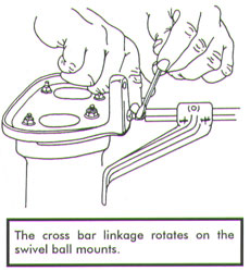
 Two
swivel ball mounts are required to support the throttle linkage cross
bar, one at each end. The cross bar swivel balls thread into the vertical
supports on each of the air cleaner bases. They are locked in position
with 8mm nuts. The supports located on the air cleaner bases have two
swivel ball mounting locations. This is to provide the engine builder
with a choice in cross bar installation height. Center Mount fan shrouds
for example, locate the fan at a higher elevation and require the use
of the top mounting holes. Thread the cross bar swivel balls and locking
nuts into their respective mounting holes. Don't lock them down just
yet. We will get back to finishing the linkage up once we have finished
the fuel rail assemblies and the throttle body/manifold assemblies have
been secured to the cylinder heads.
Two
swivel ball mounts are required to support the throttle linkage cross
bar, one at each end. The cross bar swivel balls thread into the vertical
supports on each of the air cleaner bases. They are locked in position
with 8mm nuts. The supports located on the air cleaner bases have two
swivel ball mounting locations. This is to provide the engine builder
with a choice in cross bar installation height. Center Mount fan shrouds
for example, locate the fan at a higher elevation and require the use
of the top mounting holes. Thread the cross bar swivel balls and locking
nuts into their respective mounting holes. Don't lock them down just
yet. We will get back to finishing the linkage up once we have finished
the fuel rail assemblies and the throttle body/manifold assemblies have
been secured to the cylinder heads.
Start the assembly
of the fuel rails by threading the barbed fittings into each fuel rail.
The brass fittings can be replaced with A/N fittings and stainless line.
How ever you plan on doing it, be sure to use Teflon tape on all threaded
fuel fittings. Don't let strings of Teflon precede the end of the threaded
fitting into the tapped holes. As good as Teflon is, it can raise havoc
with fuel pressure regulators and electronic fuel injectors. Make certain
to use steel hose clamps at every connection. When using rubber line,
make sure it is high pressure fuel line. When installing the brass fittings,
there are three ¼" NPT x 3/8" hose fittings and one
¼" NPT x 5/16" hose fitting. The 5/16" fitting
can be threaded in either of the two fuel rails. But when it's time
to secure the fuel rails, the rail with the 5/16" fitting will
need to be installed in the throttle body that will be closest to the
Fuel Pressure Regulator. Refer to (drawing #1 on pg.2) for illustration
on how to run your fuel system.
 Locate
the Schrader valve and 1/8" pipe plug provided in the kit. The
Schrader Valve can be installed in either of the two fuel rails, it's
best to install it where you will have the most access to it. The Schrader
Valve will be used to check the fuel pressure later on. When you have
the valve installed, the 1/8" pipe plug has been provided to plug
the hole in the other fuel rail. Remember to use Teflon tape on all
fittings. Don't over tighten, pipe threads are tapered and seal with
very little effort.
Locate
the Schrader valve and 1/8" pipe plug provided in the kit. The
Schrader Valve can be installed in either of the two fuel rails, it's
best to install it where you will have the most access to it. The Schrader
Valve will be used to check the fuel pressure later on. When you have
the valve installed, the 1/8" pipe plug has been provided to plug
the hole in the other fuel rail. Remember to use Teflon tape on all
fittings. Don't over tighten, pipe threads are tapered and seal with
very little effort.
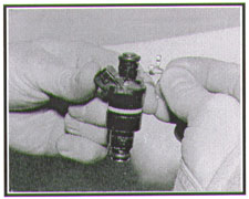 Four
clips are required to secure the injectors to the fuel rails. The
clips are pushed onto the top groove of each injector. Then push
each injector into a port on both fuel rails. To ease the installation
of the injectors into the fuel rails, it's a good idea to apply
a small amount of oil to the "O" rings. With a little
bit of pressure the injectors should slide right in. Excessive force
should not be necessary. No hammering! Once the injectors have been
pushed in, check to make sure the clips are secure over the edge
of the fuel rail. Installing the completed fuel rail assembly into
the throttle body is simply accomplished by lining up the injectors
with the ports. Then pushing them down until they feel like they
are in all of the way. They should bottom out. If not, check your
alignment. Four
clips are required to secure the injectors to the fuel rails. The
clips are pushed onto the top groove of each injector. Then push
each injector into a port on both fuel rails. To ease the installation
of the injectors into the fuel rails, it's a good idea to apply
a small amount of oil to the "O" rings. With a little
bit of pressure the injectors should slide right in. Excessive force
should not be necessary. No hammering! Once the injectors have been
pushed in, check to make sure the clips are secure over the edge
of the fuel rail. Installing the completed fuel rail assembly into
the throttle body is simply accomplished by lining up the injectors
with the ports. Then pushing them down until they feel like they
are in all of the way. They should bottom out. If not, check your
alignment. |
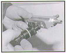 There
are two fuel rail retaining brackets, one for each throttle body. The
brackets provide a safety factor and must be installed. The brackets
are mounted to the throttle body and to the bottom of the fuel rail
with 6mm allen head bolts, washers and nyloc nuts. The retaining brackets
have two different size holes. The end with the straight cut hole is
fastened to the throttle body side.
There
are two fuel rail retaining brackets, one for each throttle body. The
brackets provide a safety factor and must be installed. The brackets
are mounted to the throttle body and to the bottom of the fuel rail
with 6mm allen head bolts, washers and nyloc nuts. The retaining brackets
have two different size holes. The end with the straight cut hole is
fastened to the throttle body side.
 The
other end with the oval shaped hole is fastened to the fuel rail side
for ease of alignment. There are two short 6 x 10mm and two long 6 x
25mm bolts. The 6 x 10mm bolts are used on the fuel rail side and the
6 x 25mm bolts on the throttle body side. Secure the bracket to the
throttle body first, using a 6 x 25mm bolt, two washers and a nut.
The
other end with the oval shaped hole is fastened to the fuel rail side
for ease of alignment. There are two short 6 x 10mm and two long 6 x
25mm bolts. The 6 x 10mm bolts are used on the fuel rail side and the
6 x 25mm bolts on the throttle body side. Secure the bracket to the
throttle body first, using a 6 x 25mm bolt, two washers and a nut.
 After
the bolt has been pushed through the throttle body from the top side,
slide the bracket on, followed by the washer and nut. Both fuel rails
have been drilled and tapped to except 6mm bolts. They require no nuts.
Line the bracket up with the fuel rail and thread in the 6 x 10mm bolt.
In the future if you need to remove the fuel rail/injector assembly,
do so from the fuel rail side of the bracket by removing the short 6mm
bolt.
After
the bolt has been pushed through the throttle body from the top side,
slide the bracket on, followed by the washer and nut. Both fuel rails
have been drilled and tapped to except 6mm bolts. They require no nuts.
Line the bracket up with the fuel rail and thread in the 6 x 10mm bolt.
In the future if you need to remove the fuel rail/injector assembly,
do so from the fuel rail side of the bracket by removing the short 6mm
bolt.
 Each
throttle body is equipped with a threaded vacuum port. The port is used
to supply vacuum (manifold pressure) to the fuel pressure regulator.
The vacuum port feeds from an internal passage that senses manifold
pressure from both intake ports. The internal passage provides a dampening
action between the intake ports which levels out the manifold pressure
signal en route to the fuel pressure regulator. Locate the two brass
barbed fittings, 1/8" NPT x ¼" hose. Wrap the threaded
ends of the fittings with Teflon tape, thread one fitting into each
vacuum port and snug'em down. Snug is enough, we're dealing with tapered
pipe threads, and over tightening could result in a cracked vacuum port
boss.
Each
throttle body is equipped with a threaded vacuum port. The port is used
to supply vacuum (manifold pressure) to the fuel pressure regulator.
The vacuum port feeds from an internal passage that senses manifold
pressure from both intake ports. The internal passage provides a dampening
action between the intake ports which levels out the manifold pressure
signal en route to the fuel pressure regulator. Locate the two brass
barbed fittings, 1/8" NPT x ¼" hose. Wrap the threaded
ends of the fittings with Teflon tape, thread one fitting into each
vacuum port and snug'em down. Snug is enough, we're dealing with tapered
pipe threads, and over tightening could result in a cracked vacuum port
boss.
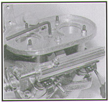
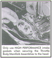 Bolt
the completed throttle body/manifold assemblies to the cylinder heads.
Before positioning the cylinder head to manifold gaskets on the cylinder
heads, make sure the sealing surface is clean and free of any old gasket
material. make certain to use the gaskets supplied in your kit. They
work a lot better than thin paper or steel gaskets. Line up the intake
manifold assemblies with the mounting studs on each head and slide them
onto the cylinder heads. Install two 8mm nuts at the base of each manifold
and slowly tighten them. The manifolds and throttle bodies will pull
inwards as the nuts are tightened. Torque the nuts down to about 14
pounds.
Bolt
the completed throttle body/manifold assemblies to the cylinder heads.
Before positioning the cylinder head to manifold gaskets on the cylinder
heads, make sure the sealing surface is clean and free of any old gasket
material. make certain to use the gaskets supplied in your kit. They
work a lot better than thin paper or steel gaskets. Line up the intake
manifold assemblies with the mounting studs on each head and slide them
onto the cylinder heads. Install two 8mm nuts at the base of each manifold
and slowly tighten them. The manifolds and throttle bodies will pull
inwards as the nuts are tightened. Torque the nuts down to about 14
pounds.
 Now
back to setting up the linkage. Assembling the linkage is a carbon copy
of the procedures followed during the installation of dual carburetors.
Start by sliding the aluminum linkage arms and throttle cable bracket
onto the steel hex bar. The arms are locked in place with allen set
screws. The throttle cable bracket locates one hex degree down from
the linkage arms. Don't tighten anything down just yet, we'll do that
once everything is lined up properly.
Now
back to setting up the linkage. Assembling the linkage is a carbon copy
of the procedures followed during the installation of dual carburetors.
Start by sliding the aluminum linkage arms and throttle cable bracket
onto the steel hex bar. The arms are locked in place with allen set
screws. The throttle cable bracket locates one hex degree down from
the linkage arms. Don't tighten anything down just yet, we'll do that
once everything is lined up properly.
Internal tension
springs are places in each end of the cross bar to aid in centering
the cross bar assembly. Place a small amount of heavy grease inside
the support holes at each end of the cross bar. Insert the tension springs
and place the right end of the hex bar over its respective cross bar
swivel ball. Push the cross bar onto the swivel ball and line up the
left side end of the cross bar with its cross bar swivel ball.
 If
it is necessary to loosen one base, do so and line up the cross bar
with the swivel mount and then re-secure the base. Hopefully your installation
of the cross bar assembly has gone smoothly up to this point. If not,
as we mentioned earlier when installing the a/c bases, there are different
variables when building an engine. The width of your engine may differ
from stock. It may be necessary to shorten or lengthen the length of
the cross bar so that enough clearance is provided on the cross bar
swivel balls. If the clearance is too far off, it may be necessary to
purchase a new cross bar with the correct length so that the installation
is done correctly.
If
it is necessary to loosen one base, do so and line up the cross bar
with the swivel mount and then re-secure the base. Hopefully your installation
of the cross bar assembly has gone smoothly up to this point. If not,
as we mentioned earlier when installing the a/c bases, there are different
variables when building an engine. The width of your engine may differ
from stock. It may be necessary to shorten or lengthen the length of
the cross bar so that enough clearance is provided on the cross bar
swivel balls. If the clearance is too far off, it may be necessary to
purchase a new cross bar with the correct length so that the installation
is done correctly.
 Now
screw the swivel ball out until the cross bar is fully supported by
the swivel ball mounts. Center the cross bar linkage assembly by rotating
the swivel balls. Adjust the length of the swivel ball mounting screws
until the cross bar is centered. Over tightening, resulting in not enough
side play, will cause the linkage bar to bind. Leave about an 1/8"
side play and tighten up the swivel ball locknuts. Make certain that
the crossbar is free to rotate on its axis. Any resistance or binding
of the cross bar can be a real problem later.
Now
screw the swivel ball out until the cross bar is fully supported by
the swivel ball mounts. Center the cross bar linkage assembly by rotating
the swivel balls. Adjust the length of the swivel ball mounting screws
until the cross bar is centered. Over tightening, resulting in not enough
side play, will cause the linkage bar to bind. Leave about an 1/8"
side play and tighten up the swivel ball locknuts. Make certain that
the crossbar is free to rotate on its axis. Any resistance or binding
of the cross bar can be a real problem later.
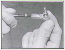 The
linkage rods and heim joints are next. There are four heim joints in
all. Two right hand and two left hand heim joints. Each side will need
one of each. The linkage rods are equipped with matching right and left
hand threads, Once installed you'll be able to fine tune your throttle
adjustments by rotating the throttle rods. After all adjustments are
made, lock them into position by tightening down the lock nuts. The
lock nuts are also supplied in right and left hand threads. Leave the
lock nuts loose for now. After the assembly of the linkage is done,
secure them to the cross bar linkage arms and the throttle body linkage
arms. You will need two open end wrenches for this operation, an 8mm
and 3/8". Thread the four shake proof nuts down on all four heim
joint connections. Not all of the way through, leave them a little loose
for now.
The
linkage rods and heim joints are next. There are four heim joints in
all. Two right hand and two left hand heim joints. Each side will need
one of each. The linkage rods are equipped with matching right and left
hand threads, Once installed you'll be able to fine tune your throttle
adjustments by rotating the throttle rods. After all adjustments are
made, lock them into position by tightening down the lock nuts. The
lock nuts are also supplied in right and left hand threads. Leave the
lock nuts loose for now. After the assembly of the linkage is done,
secure them to the cross bar linkage arms and the throttle body linkage
arms. You will need two open end wrenches for this operation, an 8mm
and 3/8". Thread the four shake proof nuts down on all four heim
joint connections. Not all of the way through, leave them a little loose
for now.
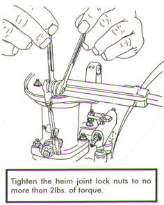 Position
the aluminum linkage arms on the cross bar so that the throttle linkage
rods are vertical when viewed from the rear of the engine. Lock the
aluminum linkage arms into position by tightening the allen set screws
to prevent the aluminum linkage arms from sliding on the crossbar. Slide
the aluminum throttle cable arm into position to line up with the throttle
cable and tighten down the set screw. Now check the installed linkage
rods, both left and right, making certain that the rods rotate freely.
Observe the way the rotation changes the length of the rod assembly.
Up to this point the linkage assembly should work freely without any
drag or binding. If there is any type of resistance, something is not
right. Go back and double check your installation. If everything is
in correct working order, tighten up the shake proof lock nuts that
secure the heim joints to the upper and lower linkage arms. Tighten
these to no more than 2 lbs. of torque.
Position
the aluminum linkage arms on the cross bar so that the throttle linkage
rods are vertical when viewed from the rear of the engine. Lock the
aluminum linkage arms into position by tightening the allen set screws
to prevent the aluminum linkage arms from sliding on the crossbar. Slide
the aluminum throttle cable arm into position to line up with the throttle
cable and tighten down the set screw. Now check the installed linkage
rods, both left and right, making certain that the rods rotate freely.
Observe the way the rotation changes the length of the rod assembly.
Up to this point the linkage assembly should work freely without any
drag or binding. If there is any type of resistance, something is not
right. Go back and double check your installation. If everything is
in correct working order, tighten up the shake proof lock nuts that
secure the heim joints to the upper and lower linkage arms. Tighten
these to no more than 2 lbs. of torque.
The trick now
is to get your linkage aligned to match your preset throttle bodies.
Adjust the throttle linkage rods by rotating in right or left hand directions,
until both throttle arms are resting on the idle speed set screws. By
rotating the linkage rods you'll be able to extend or shorten the length
of the rods. This will allow you to match the preset throttle bodies.
Do not change the position of the idle speed set screws
to match your linkage. You already set both throttle bodies to the same
opening. Adjust the linkage to match the throttle bodies.
When you think
that you've got the linkage dialed in, push the aluminum throttle arm
downwards and watch the linkage arms as they move from closed to open.
If one throttle body "leads" the other, you've got some more
dialing in to do. The opening and closing throttle action of fuel injection
with dual throttle bodies is just like dual carburetors, it has to be
precise. So play with your linkage until it works like a Swiss watch.
Don't try to reinvent the linkage system. Simply adjust it to match
your preset throttle bodies and tighten up the four
lock nuts on the throttle linkage rods.
Look over the
complete assembly carefully prior to connecting the throttle cable.
The cross bar linkage assembly should work accurately and freely. Both
throttle bodies should snap to closed position when the linkage is released
without protest.
Connect the throttle
cable. Have someone operate the throttle pedal from inside the car while
you watch the action taking place in the engine compartment. Make certain
that the pedal attains the end of its "stroke" at the same
time or slightly before the throttle reaches full open. Excessive travel
of the throttle pedal can bend the throttle linkage. It may be necessary
to install a throttle pedal stop to control or limit pedal movement.
If the drag of the throttle cable and pedal seem to be slowing down
the closing action of the linkage, it may be necessary to install two
helper throttle return springs. The helper springs will provide a safety
factor and should be seriously considered for use on any type of vehicle.
The slight amount of increase in throttle pressure will never be noticed.
The rest of the
fuel system can now be completed. Up to this point all fuel line (hard
line), fuel pump/fuel filter, throttle body/manifold assembly and throttle
linkage have been installed. The main line (previously installed) needs
to be hooked up to the front of the passenger side fuel rail (flywheel
side). Keep in mind, your fuel system may differ from that of what is
being described, you may have decided to route your system differently.
Use the supplied 3/8" fuel line to make the required connections.
Now run a line from the back of the passenger side fuel rail (pulley
side) across the engine to the back of the drivers side fuel rail. All
connections up to this point should have been done with 3/8" line.
The remaining connection needs to be 5/16" line, and it runs from
the front of the drivers side fuel rail (flywheel side) to the inlet
side of the Fuel Pressure Regulator. Connect the outlet side of the
regulator to the return line going to the fuel tank. This will complete
the fuel system. Refer back to (drawing #1 on pg. 2) for illustration.
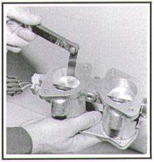
The two 1/8"
NPT x ¼" hose barbed fittings threaded into the throttle
bodies will now be used to supply vacuum to the fuel pressure regulator.
A ¼" brass "T" is used to connect both throttle
bodies together to supply the needed vacuum to the regulator. It's important
to use the "T" when hooking up the vacuum lines in an effort
to maximize and smooth out the engine vacuum signals. If only one barrel
is connected to the pressure regulator, the signal will pulse and create
undesired effects on the fuel pressure. When functioning properly, the
fuel pressure regulator uses manifold pressure to reduce fuel pressure
at an idle speed and increase fuel pressure during peak requirements.
Refer to (drawing #2) on this page for illustration on the vacuum line
system.
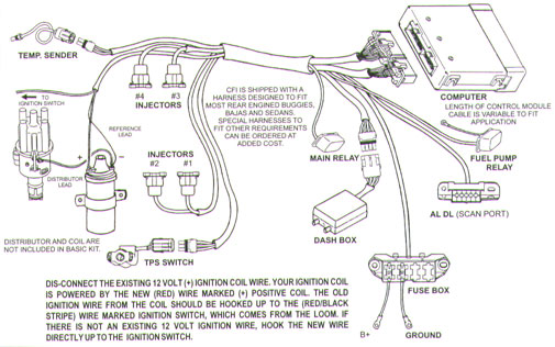
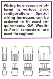
 The
wiring harnesses supplied by CB Performance are complete and ready to
snap on. The GM Weather-Pack connectors are designed for easy installation.
Each connector is marked as to usage and keyed to fit only one application.
Data is fed to the computer by two engine mounted sensors.
The
wiring harnesses supplied by CB Performance are complete and ready to
snap on. The GM Weather-Pack connectors are designed for easy installation.
Each connector is marked as to usage and keyed to fit only one application.
Data is fed to the computer by two engine mounted sensors.
 1.
TPS - The throttle position switch is mounted on the right side throttle
body. The exact throttle position in degrees is reported to the computer
while the engine is switched on.
1.
TPS - The throttle position switch is mounted on the right side throttle
body. The exact throttle position in degrees is reported to the computer
while the engine is switched on.
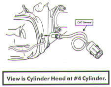
2. CHT - The cylinder
head temperature sensor monitors the temperature of the left side cylinder
head. The computer uses information to adjust the air/fuel mixture to
compensate for cold start, warm up and fuel delivery during high engine
temperature. If your cylinder head is not equipped with an OEM injection
boss, it will be necessary to drill and tap (1/8" NPT.) the left
side cylinder head as shown to provide a mounting location for the CHT.
Drawing
#3
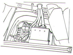
 Your
computer (ECM) is mounted inside a sturdy aluminum chassis. This enclosure
is rugged and designed to withstand severe shock and rapid temperature
changes. However the outer shell is not moisture proof.
If you plan on operating your vehicle in wet or moist conditions, it's
advisable to mount your computer in the driest possible location and
provide further moisture protection in the form of a heavy duty plastic
zip cover or outer enclosure. Various types of plastic snap together
boxes and trays are available for this purpose. Aluminum boxes in various
sizes are also available that provide a secure moisture resistant installation.
Your
computer (ECM) is mounted inside a sturdy aluminum chassis. This enclosure
is rugged and designed to withstand severe shock and rapid temperature
changes. However the outer shell is not moisture proof.
If you plan on operating your vehicle in wet or moist conditions, it's
advisable to mount your computer in the driest possible location and
provide further moisture protection in the form of a heavy duty plastic
zip cover or outer enclosure. Various types of plastic snap together
boxes and trays are available for this purpose. Aluminum boxes in various
sizes are also available that provide a secure moisture resistant installation.
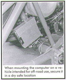 The
computer should be mounted away from engine heat and in a protected
location. Locate the wire connector and of the computer downward if
the computer is to be mounted vertically. This will help keep any foreign
debris away from the terminals. Check the length of the harness before
you mount your computer. This kit doesn't include wire stretchers, so
plan your harness layout before you mount the computer, fuse block,
or other electronic components. When your satisfied with the harness
layout, mount the computer in as dry and secure a location as possible.
And no, the computer won't work under water! If mounted properly, it's
moisture resistant, but not water proof.
The
computer should be mounted away from engine heat and in a protected
location. Locate the wire connector and of the computer downward if
the computer is to be mounted vertically. This will help keep any foreign
debris away from the terminals. Check the length of the harness before
you mount your computer. This kit doesn't include wire stretchers, so
plan your harness layout before you mount the computer, fuse block,
or other electronic components. When your satisfied with the harness
layout, mount the computer in as dry and secure a location as possible.
And no, the computer won't work under water! If mounted properly, it's
moisture resistant, but not water proof.
Do no
use silicon based sealers in an attempt to prevent moisture from entering
the computer. Silicon sealers contain acetic acid. Acetic acid emits
corrosive gasses during its curing stage. These gasses can cause severe
corrosion of the computer and wiring terminals. It's effect on solder
joints is well documented.
Your computer
has two male connector plugs. A large one and a small one. The female
connectors on the harness are keyed and will only plug in one way. The
connectors are held in place by tension snaps. Depressing the snap lever
releases the connector to allow it to be removed.
The ALDL (scan
port) connector can be located in any convenient location. The ALDL
provides system access to allow the use of a diagnostic scanner. Your
CFI system is GM compatible and can be accessed under GM 1990 L 05 5
27R. The scan will indicate engine RPM, temperature, TPS setting, injector
pulse rate and condition of the voltage system.
Position and mount
the fuse block in a dry, convenient location that provides easy access
for servicing the fuses. Each CFI system includes two relays. They are
connected to special five pin terminal plugs that only plug in one way.
Mount the relays in a protected area. One relay operates the fuel pump.
The fuel pump relay is equipped with a fuel pump lead wire.
The lead wire
is marked (+) positive, and fitted with a round lug ring. It connects
to the (+) positive terminal on the fuel pump. The (-) negative terminal
on the fuel pump must be routed to ground. Use the supplied piece of
secure it to a good clean ground.
The fuel pump
is activated by the computer. A special timing circuit in the computer
will turn the fuel pump off when the ignition is left on with the engine
not running. The computer will also turn the fuel pump off should the
engine stall and the ignition is left on. The fuel pump will restart
when the ignition is switched off, and then back on.
|
| The
computer can be located under or behind the rear seat in a VW
Sedan. Do not mount the computer in the
engine compartment. Excessive heat will damage the
internal components. |
Connect the four
injector connectors coming from the harness. Each connector is numbered
with a corresponding cylinder number. The plastic connectors simply
push onto the injectors. They are held in position by wire snaps. Make
certain to position the wires so that they don't interfere with the
throttle linkage. Tie the wires with nyties to prevent them from being
pulled into the cooling fan (if necessary). Connect the red wire marked
(+) positive, to the hot side (12 volt) of the ignition coil. Connect
the fused ignition lead to the "switched" hot side of the
ignition switch.
CB's Ultra Competition
Fuel Injection can be used with most any type of ignition with the exception
of magnetos. Breaker point, solid state, crank fired and other ignition
systems can be used. A 40,000 volt MAGNASPARK HEI ignition system is
ideal for use with Competition Fuel Injection. For those using MSD or
Compufire DIS-IX systems, (refer to pgs. 11-13) for special installation
guides on these systems.
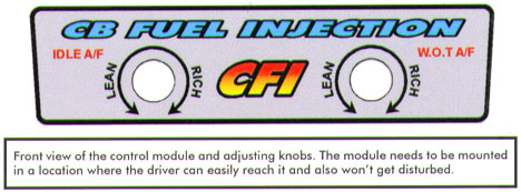
The control module
connects to the main harness with an extension cord. The cord is fitted
with a four wire Weather-Pack connector. The module needs to be mounted
in a location where the driver can reach it easily and where it won't
get in the way or get disturbed. The module contains a microprocessor
that allows you to adjust the idle speed and upper end fuel curves.
The knobs on the
control module are labeled Idle A/F and W.O.T A/F. The Idle A/F knob
is used to set the idle and slow speed air fuel mixture. Turning the
knob to the left (counter clockwise) leans the mixture. Turning the
knob in the other direction (clock-wise) richens the air fuel mixture.
The W.O.T A/F
knob is used to set the midrange and high speed fuel curves. Counter
clockwise rotation leans the midrange and high speed fuel curve. Counter
clockwise rotation leans the midrange and high speed fuel curve. Clockwise
rotation richens the midrange and high speed fuel curve.
The control module
has been preset to an established fuel curve. Try the preset fuel curve
before altering it. The knobs function on 10 turns, stop to stop. This
allows you a lot of latitude to dial in the exact air fuel curve your
engine requires for peak performance.
When you are at
the point to start tuning your engine with the control module, refer
back to this section for important tuning procedures! Keep in mind that
these steps are based on idle fuel pressures of 45-50 P.S.I.
The idle knob
needs to be set with the engine running at idle speed. Allow the engine
to reach a normal operating temperature before any adjustments are made.
When the engine is warm, simply begin to lean the idle control knob
until the engine RPM begins to fall off. This is done by rotating the
knob counter clockwise. Once the idle begins to fall off, turn the knob
in the other direction. This will start to richen up the idle circuit.
When the engine begins to raise in RPM and starts to stabilize, you're
there. The adjustment is just like adjusting the mixture screws on a
carburetor, only you are able to adjust all 4 cylinders at one time.
The W.O.T A/F
knob is next. To set the W.O.T knob, you will need some place to drive
your vehicle. This is not an idle setting. In order to achieve the best
setting, it must be adjusted under a wide open throttle situation to
get the best power from your engine. This control determines how much
fuel is delivered to the engine under the load of wide open throttle.
Sitting in your driveway rapping up the engine will no work. It has
to be under a load. This setting is just like changing the main jets.
If your adjustment is too rich, your engine's power curve will mush
out, or flatten during high RPM operation. Black smoke out of the exhaust
during acceleration is a certain indication of an over rich condition.
If the air/fuel mixture is too lean, the engine will hunt during cruise
speed and stumble or hesitate from first midrange acceleration. A lean
condition will create a weak upper end RPM response. Increased exhaust
temperature is another indication of a lean condition. Some place between
too rich or too lean, lies the perfect fuel curve for your engine and
driving style.
Important
Updated Information
When
using an aftermarket ignition system, such as MSD or a complete COMPUFIRE
DIS-IX system, refer to the following pages for important installation
procedures and wiring diagrams. In instances where engine "run
on" is occurring (when engine stays running when you turn key off)
there is a wiring diagram to guide you through curing this simple problem.
Set the fuel pressure
to 60 P.S.I with the engine not running. This will provide a "get
it" running setting. The computer activated fuel pump can complicate
this procedure, because the pump will automatically shut off in less
then one second. Disconnect the wire leading to the fuel pump. This
will give you time to set the fuel pressure and check the fuel system
for any links.
The fuel pressure
is set by removing the cap nut from the top of the fuel pressure regulator
and loosening the lock nut on the threaded shaft. Fuel pressure is increased
by rotating the adjusting shaft clockwise. Less fuel pressure by rotating
the shaft counter clockwise. Pressure can be checked at the Schrader
valve located in the fuel rail. If you don't have a special fuel injection
kit, a tire pressure gauge will get the job accomplished. When you have
the pressure set, lock the jam nut and replace the cap nut. Remove the
jumper wire used to hot wire the fuel pump and reconnect the fuel pump
to the fuel pump relay.
Start your engine,
your fuel pressure will drop depending on the amount of vacuum produced
by your engine. Camshafts with less duration will produce more vacuum
which in turn will drop your fuel pressure accordingly. Vice versa for
engines with longer duration camshafts. Stabilize your engine RPM high
enough so that it can hold a steady idle.
 Your
next procedure is to use a Uni-Syn gauge and synchronize your throttle
bodies. It is very important to get your bodies in sync. Stable fuel
pressure is greatly influenced by a set of unbalanced throttle bodies.
Once you have achieved a balanced situation, stabilize your engine idle
between 800-900 RPM. Go back and readjust your fuel pressure to 45-50
P.S.I. Balancing the throttle bodies and adjusting the fuel pressure
are two of the most important steps to installing CFI. Please don't
try to guess with these adjustments.
Your
next procedure is to use a Uni-Syn gauge and synchronize your throttle
bodies. It is very important to get your bodies in sync. Stable fuel
pressure is greatly influenced by a set of unbalanced throttle bodies.
Once you have achieved a balanced situation, stabilize your engine idle
between 800-900 RPM. Go back and readjust your fuel pressure to 45-50
P.S.I. Balancing the throttle bodies and adjusting the fuel pressure
are two of the most important steps to installing CFI. Please don't
try to guess with these adjustments.
Double check your
installation for any loose ends or leaks, hopefully everything checks
out all right. Pick everything up and make sure you don't have tools
lying around on the vehicle. It's time for a test drive. Refer back
to (pg.10) for important tuning adjustment instructions using the dash
module. Good Luck!
Important
Notice about your car's fuel system
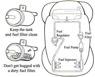
Fuel contamination
can be the cause of a poorly running engine. Even though your gas tank
is relatively new, it can still contain enough dirt, metal fillings
and other debris to plug up a kitchen sink. A close inspection of most
any dune buggy gas tank will quickly illustrate the end result of contaminated
storage tanks. Most five gallon fuel cans often have junk waiting in
the bottom to end up in your fuel tank. Make sure this doesn't get you
stranded.
Dirt, sand and
other sludge builds up in the filter as the fuel is circulated through
the system. The filter will eventually clog to the point that the fuel
will only trickle through the filter. When this happens the engine will
idle, and depending on the amount of fuel flow, might even run at mid-speed.
Full throttle operation with a partially plugged filter will result
in serious fuel starvation. Your engine will tell you about this by
popping and snapping out of the exhaust pipe as it goes lean due to
a lack of fuel.
This condition
is often misread as burnt points, fouled spark plugs and even tight
valves. Check your cars fuel filter on a regular basis. Check the fuel
filter as often as you check your oil if you operate your engine in
dirty conditions. Also make sure that the fuel filter and fuel pump
are installed in the correct order. First the fuel filter and then the
fuel pump. The filter can be quickly replaced, and if that doesn't solve
the problem, work your way through the following Trouble Shooting Guide.
Trouble
Shooting CFI
CFI is a simplified,
easy to understand electronic injection system. Most of the bells, whistles,
and complications normally attached to electronic fuel injection have
been eliminated from this new CFI package. The logic for CFI is solid
state digital. The only electronic components with moving parts that
are used in the actual injection system are the fuel injectors, the
TPS, two relays, and the fuel pump. All other components such as the
computer and engine temperature sensor are solid state.
The fastest and
most accurate way to check the electronic system is with the use of
a GM compatible scanner. The scanner will supply information concerning
but not limited to: TPS setting, engine temperature, injector pulse
rate, RPM, system voltage and possible trouble codes. This range of
information can be accessed under GM 1990 L 05 5 27 R. The use of the
scanner requires technical training which is normally supplied by the
manufacturer of the unit. Most modern automotive repair shops are equipped
with scanners and can quickly perform the service for you.
You can however,
run a series of checks by using an inexpensive digital multi meter.
Other basic testing can be accomplished with a non-powered test light.
A complete systems check should begin by confirming that your electrical
system maintains a voltage range of 12 to 14 volts. This range of voltage
must hold true during switch on only, cranking and running modes. Low
voltage, less than 12 volts, can cause the computer to misread the engine
generated signals. This will result in faulty engine performance. Other
problems that accompany low voltage center around the fact that the
electronic relays in this system are designed to function in a prescribed
voltage range. Initial low voltage due to low battery reserve can cause
hard starting problems. However, once started, and proper system voltage
is restored and maintained, by the alternator, the engine will run as
it should.
Make certain that
your electrical system including the battery is up to specs. If necessary
use a hydrometer to test your battery. If jump starting or charging
is required, DO NOT USE 24 VOLT CHARGING EQUIPMENT.
CFI has been designed
to operate with most ignition systems. The computer triggers the injectors
based on signals received from the distributor. The computer fires all
four injectors at the same time. This event happens once each engine
revolution. The computer varies the length of time that the injectors
are opened. This determines how much fuel is squirted into the engine
during each revolution. The time that the injectors are open is referred
to as the pulse width. The injector pulse width is measured in milliseconds.
The injector pulse width or rate, will vary from 1.7 milliseconds during
idle speed to over 9.0 milliseconds at full throttle.
The injector pulse
width is a product of engine temperature, RPM, and TPS settings. During
cold start, the injector pulse rate is longer to supply the additional
fuel required to run the engine. The injector pulse rate is longer to
supply the additional fuel required to run the engine. The injector
pulse rate is automatically shortened as the engine warms. The injectors
are turned off during rapid deceleration.
The easiest way
to see if the injectors are actually firing, (squirting fuel) is to
remove a complete fuel rail assembly and crank the engine over. Make
certain to pull the coil wire before cranking the engine because you
only need a quick visual check of each injector. If one or more injectors
fail to produce a spray pattern on command, you can use a test light
or a digital multi meter to verify an electrical pulse. This is done
by removing the injector wiring connectors from all of the
injectors. Attach the test instrument to both leeds of
one injector. An easier way, if you have the special test equipment,
is to use a node light for the test. A node light can be plugged into
an injector connector to supply a visual indication of an electrical
pulse at that location.
If the test device
fails to indicate a 12 volt pulse during engine cranking its possible
that you've got some type of wiring problem. Check the other injectors
to see if you have a partial or complete system failure.
If you determine
that an electrical pulse is present at each injector, and the injector
does not produce a spray pattern, check the fuel pressure. Is pressure
present at each injector? Are the injectors plugged? If not, check the
fuel pump to make certain that it is functioning when turned on. Remember,
the fuel is on a timed safety circuit. If you require a longer length
of time to check the fuel pressure, use jumper wires to run the fuel
pump. Make certain to first disconnect the fuel pump from the fuel pump
relay before you hook up the jumper wires.
But slow down
before you rip up the electrical system. Fuel delivery problems can
often be traced to basic big thumb problems such as a plugged fuel filter.
A filter that is completely plugged is easy to spot. The pump runs but
nothing comes out of the pressure end. A partially plugged filter is
a little harder to deal with because it can allow enough fuel to trickle
through the system to idle the engine. Slight opening of the throttle
will result in a typical lean condition with lots of snapping and popping
out the throttle bodies and exhaust. Your best shot here is to remove
and clean the fuel tank and install a new filter. Before you do all
of that, make certain that you've got enough fuel in the tank to get
around the block.
If pressure is
present at the lines, and the injectors don't seem to be responsive,
it's time to check the red wires at the injectors. Each injector is
connected to a common fused circuit. 12 volts should be present and
continuous at each red injector terminal with ignition switch turned
on. If 12 volts is not indicated, check the fuse and power supply to
determine where the fault or break in the power supply lies. Don't forget
to remove the fuel pump jumper wires before continuing your search for
fuel delivery problems.
The blue wires
at injectors 1 and 2 are connected to terminal C 15 at the computer.
Injectors 3 and 4 are connected via blue wires to computer terminal
D 15. The computer grounds these circuits on command, thereby energizing
the injectors. One way to determine if the computer is signaling the
injectors to open is as follows: disconnect all of the injector terminals
from the injectors. Connect a 12 volt test light across one injector
terminal. Crank the engine over, and observe the test light. It should
wink on briefly with every complete rotation of the engine. A multi
meter can also be used for this test.
If the test light
shows no response to engine rotation, check the red wire at the injector
terminal to verify that 12 volts is present at all times when the ignition
switch is on. If voltage is not present, check the complete circuit
to origination. Check computer terminals C 15 and D 15 to make certain
that the wires are making contact with the computer pins. Use a continuity
tester for this check. Remove the wiring connectors from the computer.
Examine computer pins C 15 and D 15 to make certain that they are not
bent, thereby preventing contact with the connector. Never
use direct battery voltage to test computer circuits.
An improperly
grounded main system ground can cause partial or total loss of injector
function. Make certain the main system ground is bolted or screwed to
the chassis ground. Use a continuity tester to verify ground to computer
terminals A 11, A 12, and D 11. It is not necessary to provide a separate
ground wire for the computer housing or chassis. Computer terminal A
12 provides a main ground circuit. Caution, never use direct
battery current to test computer circuits. Always use a continuity tester
for this purpose. The use of direct battery or power supply
current to check computer circuits will most always result in un repairable
damage to the computer.
The dash mounted
tuning module connects to the main harness with a four wire connector.
The wires are color coded to facilitate inspection procedures. The green
wire, terminal D at the connector provides varying voltage (1 to 5 volts)
to computer terminal C 11. This is the MAP circuit. The left side knob
controls the amount of voltage supplied to this wire. Clockwise rotation
increases the voltage. Counter clockwise rotation decreases the voltage.
Normal idle speed voltage at C 11 varies between 1.25 and 2 volts. Voltage
settings higher than 2 during idle speed will produce an over rich condition.
This circuit can be scanned under MAP. A multi meter can be used at
computer C 11 or terminal D at the plug.
The right side
knob on the dash module provides enrichment information to the computer
during midrange and W.O.T. The high speed system is made richer by turning
the knob clockwise. This information is also routed to the computer
via green wire to connector terminal B and then to computer terminal
C 11. Initial upper end voltage should be set at 4.25 volts. This can
be checked with a scanner or multi meter.
Computer terminal
C 14 supplies a 5 volt reference to the dash module via the tan wire
and connector terminal B. This circuit is controlled by the TPS switch.
A varying voltage between 1 and 5 volts feeds into the dash module from
computer terminal C 13 via green wire and connector D. Average voltage
at C 13 with throttles closed is .95 to 1 volt. Full throttle settings
with the right side knob advanced should read 4.75 to 5 volts. TPS voltage
is scannable or can be monitored with a multi meter.
The scanner will
also provide throttle setting information in degrees of throttle plate
advance as well as voltage. A TPS switch set in an advanced position
an cause an engine to idle uncontrollably rich. Initial TPS voltage
should not exceed 1.10 volts. Do not advance your TPS beyond its original
factory setting. An unbalanced set of throttle bodies can create a serious
idle speed over rich condition, here's how.
If the right side
butterflies are significantly advanced (opened) ahead of the left side
butterflies, the TPS will indicate an advanced throttle setting. The
advanced throttle position will tell the computer to richen the mixture
in order to begin acceleration. For this and other reasons, it's imperative
to proper engine operation that the throttle bodies be in close sync.
A final check of the throttle body synchronization must be done with
a Uni-Syn gauge. The procedure is similar to balancing a set of dual
carburetors. TPS voltage at idle speed must not exceed 1.10 volts. This
voltage can be probed at the 3 wire TPS plug, terminal B, or at computer
terminal C 13.
If the engine
refuses to run, check C 14 with the switch on. It should produce a constant
5 volt reference voltage. Make certain that the D 2 sensor ground is
functional. Check C 11 with switch on for idle speed voltage. It should
read 1.25 to 2.00 volts. Advance the throttle. The voltage at C 11 should
advance to 4.75 to 5.00 volts at W.O.T. If voltage is not present at
C 11 recheck complete power supply to computer.
An over rich condition
can be caused by a short to ground or failed ETS. C 10 should indicate
approximately 3,400 OHMS at 70 degrees F. The accompanying chart will
provide a range of temperature to OHM values. A grounded ETS wire will
result in a reading of more than 100,000 OHMS at terminal C 10. This
will cause the engine to run super rich. Conversely, a broken or open
lead to C 10 will create a lean condition resulting in hard storing
due to cold weather. An open or broken lead is indicated by a reading
of zero OHMS at C 10. The engine will run ok after it warms. So if you
have a hard cold start problem, check the OHM reading at C 10. When
using the engine temperature chart keep in mind that it represents only
approximate resistance values.
Tuning
Hints -
Most VW engines
run in the 1.60 to 4.25 MAP voltage range. Higher revving race engines
can be further richened on the upper end by increasing the high end
MAP output. Here's where the stomp tuning comes in because you can only
set the upper end MAP voltage during full throttle with the engine under
load. Your best shot for a realistic dial is in the fourth gear, which
gives you adequate time to "feel the engine". Third gear is
second best, but you can use it when suitable high speed terrain is
limited. The problem with power tuning in third gear is that your engine
will actually use more fuel when it's in fourth gear. Why? Because it's
pulling harder, a lot harder. So if you attempt to use third gear to
dial it in, it's possible that your engine could run out of fuel at
higher revs during a hard pull in fourth gear.
A lean condition
will sometimes announce itself as the engine hunts or surges while traveling
at constant highway speeds. An additional hint of a lean condition is
a stumble from first acceleration, followed by possible snapping back
through the throttle bodies as the engine attempts to gain speed. The
stumble and snapping is the engines way of saving, help....give me some
more fuel! Trying to run an engine to lean will cause the engine to
run hot. Chrome exhaust pipes often turn dark blue when an engine is
pushed to high RPM while running a dangerously lean fuel mixture.
On the other side
of the fuel equation, full rich often isn't the answer. You'll quickly
find that an engine that is too fat on the upper end of the air/fuel
curve will sort of mush out at high RPM. A slight tad down (counter
clockwise on the right side knob) from rich will usually bring in that
crisp, snappy just feel right. When you've got it right you can sense
it from the seat of your pants as the engine lights up and screams to
life.
Don't expect your
new CFI kit to work miracles. It won't restore lost power due to worn
engine parts or ignition timing that was set by guesstimate. So do your
home work, adjust your valves, set the timing, fix those exhaust leaks
and tie down all the loose wires before before you blast off. Make certain
that your engine is ready for the task ahead. When you get in running,
don't misinterpret high speed valve float. If your engine flattens out
and lays down on the upper end it isn't necessarily the fault of your
new CFI package. Check out those valve springs. When your gonna wind
it over 4700 RPM you'll need some type of high rev valve springs, because
stock VW springs just won't do the job. Dual valve springs will be required
for anything over 7,000 RPM.
As previously
stated, you can't dial in the upper end fuel curve while parked at the
curb, or while just cruising down the street with a light load on the
engine. But you can dial in the bottom end by just turning the left
knob on the control module until your engine idles smoothly. Then with
the idle speed set, try an easy transition into fourth gear. If the
engine bogs or snaps out the pipe as it comes under load, increase the
air/fuel mixture by turning the left knob clockwise. If you manage to
get it too rich, the engine will quickly tell you by emitting black
smoke and performing on the lazy side. Play with the low speed adjustment
until the engine idles smoothly, and moves the car forward at first
acceleration and slow speed without hesitation.
Dialing in the
bottom end is a snap. Upper end tuning poses a challenge because like
we said, you can only find that magic mix of air and fuel that your
engine requires for upper end peak efficiency by repeated full throttle
testing. Old fashioned trial and error. And you can't power tune on
a public street because serious power tuning usually puts you over the
speed limit.
An upper end dial
in session is really what it is all about. It's where all of the bench
racing stops and the real stuff starts. This is the reason that you
spent the last three months getting your engine ready! Power tuning
requires that you first locate a 100% unrestricted "OFF ROAD"
area. Race tracks and sand dunes work just great. You're going to be
traveling at high rates of speed during the tuning procedure and the
chosen test route must be well sorted out. Safety first... Drive through
the test area once or twice at low speed, check it out, look it over
before beginning your power tuning procedures.
Competition
Injection Wiring Diagrams